Home :: SONY :: Sony CD/DVD/Blu-Ray/Network Media Players, Recorders Service Manuals :: Sony BDP-BX59/S590/S490 Service Manual

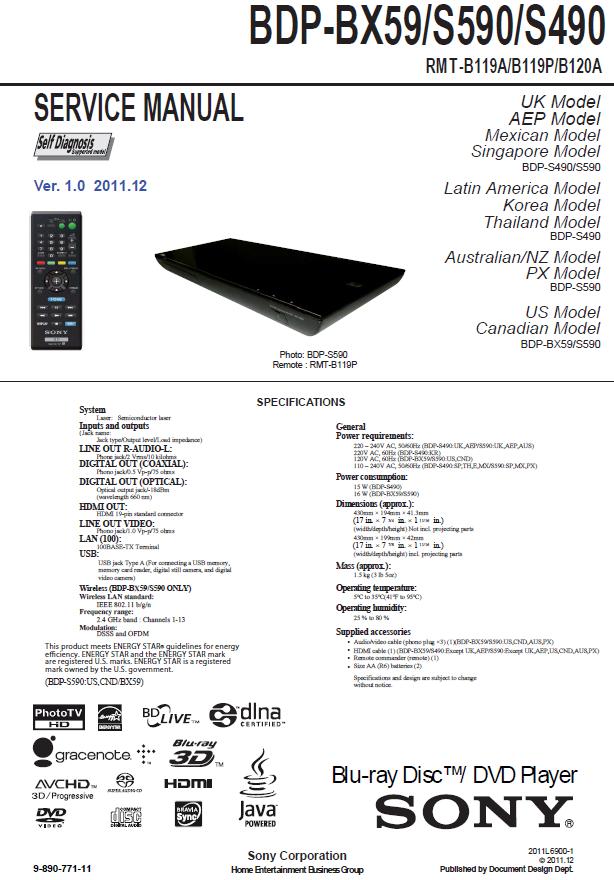
Sony BDP-BX59/S590/S490 Service Manual

Sony BDP-BX59/S590/S490 Service Manual
Sony Blu-ray Disc/DVD Player BDP-BX59/BDP-S590/BDP-S490 Service Manual

Contents:
1. SERVICE NOTE
1-1. Disc Removal Procedure If The Tray Cannot Be
Ejected (Forced Ejection) .............................................................. 1-1
1-2. Work when optical device are replaced ........................................... 1-1
1-3. Test Disc ................................................................................. ....... 1-2
1-3-1. Operation and Display ...................................... ...................... 1-2
1-3-2. Menu functions ......................... .............................................. 1-9
1-4. Drive Repairing................................................................................ 1-15
1-4-1. Preparation .............................................................................. 1-15
1-4-2. Checking Flow ~ Drive (BU) section ~ .................................... 1-15
1-4-3. BU Check Flow [zz] ~ ............................................................. 1-16
1-4-4. BU (Optical Block) Repair Guide ............................................ 1-16
1-4-5. BU Adjustment Flow [yy] ~ ..................................................... 1-17
1-4-6. KEM-480AAA/C2RP Packing Spec ........................................ 1-17
1-4-7. KEM-480AAA/C2RP Packing .................................................. 1-18
1-4-8. BU Data Decode Jig ............................................................... 1-19
1-4-9. Loading For Service ................................................................ 1-20
1-4-10. Laser Caution Label ................................................................ 1-22
1-5. Assembly Caution .......................................................................... 1-23
2. DISASSEMBLY
2-1. Disassembly Flow .......................................................................... 2-1
2-2. Side And Top Panel ........................................................................ 2 -1
2-3. Tray Cover Assy .............................................................................. 2-2
2-4. Front Panel And Top Bracket ........................................................... 2-2
2-5. FR-320 Board, FL-211 Board And WLAN Module ............................2-3
2-6. Switching Regulator ........................................................................ 2-3
2-7. MB-144 Board ................................................................................ 2-4
2-8. OP-020 Board And BD Drive ........................................................... 2-4
2-9. Circuit Board Location ................................................................... 2-5E
3. BLOCK DIAGRAMS
3-1. Overall Block Diagram .................................................................... 3-1
3-2. DSP Block Diagram ........................................................................ 3-2
3-3. AV OUT Block Digram ..................................................................... 3-3
3-4. USB/ETHER/WIFI Block Diagram .................................................. 3-4
3-5. Power Block Diagram ................................................................. 3-5E
4. SCHEMATIC DIAGRAM
4-1. This Note Is Common For Schematic Diagrams .............................. 4-1
4-2. Frame Schematic Diagram...............................................................4-2
4-3. FR-320 Board (FRONT BOARD) Schematic Diagram ..................... 4-3
4-4. FR-320 Board (FRONT USB) Schematic Diagram .......................... 4-4
4-5. FL-211 Board Schematic Diagram .................................................. 4-5
4-6. OP-020 Board Schematic Diagram ................................................. 4-6
4-7. MB-144 Board (DDR 3 A)
Schematic Diagram (1/12) .............................................................. 4-7
4-8. MB-144 Board (DDR 3 B)
Schematic Diagram (2/12) .............................................................. 4-8
4-9. MB-144 Board (POWER)
Schematic Diagram (3/12) .............................................................. 4-9
4-10.MB-144 Board (CLK/POWER2)
Schematic Diagram (4/12) ............................................................. 4-10
4-11. MB-144 Board (FLASH/HOST)
Schematic Diagram (5/12) ............................................................. 4-11
4-12.MB-144 Board (USB)
Schematic Diagram (6/12) ............................................................. 4-12
4-13.MB-144 Board (HDMI/VIDEO)
Schematic Diagram (7/12) ............................................................. 4-13
4-14.MB-144 Board (ETHERNET)
Schematic Diagram (8/12) ............................................................. 4-14
4-15.MB-144 Board (AUDIO/VIDEO)
Schematic Diagram (9/12) ............................................................. 4-15
4-16.MB-144 Board (GPIO/JTAG)
Schematic Diagram (10/12) ........................................................... 4-16
4-17.MB-144 Board (FE_POWER/OP)
Schematic Diagram (11/12) ............................................................ 4-17
4-18.MB-144 Board (FE_POWER/MOTOR DRIVE)
Schematic Diagram (12/12) ........................................................... 4-18
4-19.Waveforms ...................................................................................... 4-19E
5. PRINTED WIRING BOARDS
5-1. This Note Is Common For Printed Wiring Boards .......................... 5-1
5-2. FR-320 Board (FRONT RIGHT) Printed Wiring Board.................... 5-2
5-3. FL-211 Board (FRONT LEFT) and
OP-020 Board (OPTICAL) Printed Wiring Board ............................5-3
5-4. MB-144 Board(MAIN)
Printed Wiring Board (Side A) ......................................................... 5-4
5-5. MB-144 Board (MAIN)
Printed Wiring Board (Side B) ....................................................... 5-5E
6. IC PIN FUNCTION DESCRIPTION .................................... 6-1
7. SERVICE MODE ................................................................ 7-1
8. ERROR LOG LIST ............................................................. 8-1
9. TROUBLESHOOTING......................................................... 9-1
10. REPAIR PARTS LIST
10-1.Exploded Views ............................................................................ 10-1
10-1-1. Case Section ......................................................................... 10-1
10-1-2. Main Chassis Section............................................................. 10-2
10-1-3. BD Section.............................................................................. 10-3
10-1-4. Accessories ........................................................................... 10-4
10-2.Electrical Parts List ....................................................................... 10-5
Details
SKU SKU930911
Pages: ................................. 110
Format: ................................ PDF document
Packing: ............................... ZIP-Archive
Language: ............................ English
 
Our price: $9.95 (7.96)
Options
Quantity 1 (this product is downloadable)
Download Size 6.17MB
Download Time
Less than 1 minute @ 1.8mbs
[Change Connection Speed]

Customers also bought

SF-9500
Pioneer CX-938 Service Manual
Pioneer VSX-D209 Service Manual
SF-9500 Pioneer CX-938 Service Manual Pioneer VSX-D209 Service Manual
$4.95
$9.95
$9.95
 
XR-C5100/XR-C5100R/XR-C5103R
DCR-VX2200E
Marantz SR4500/PS4500 Service Manual
XR-C5100/XR-C5100R/XR-C5103R DCR-VX2200E Marantz SR4500/PS4500 Service Manual
$9.95
$9.95
$9.95
 
FujiFilm A860 Service Manual
Canon POD Deck Lite-B1 Service Manual
FujiFilm A860 Service Manual Canon POD Deck Lite-B1 Service Manual
$9.95
$9.95