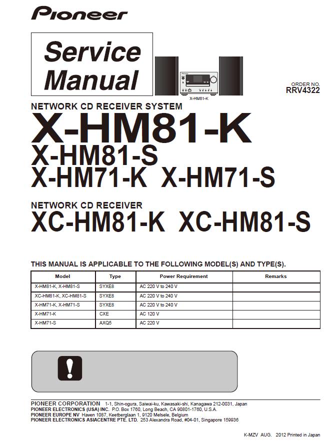
Pioneer NETWORK CD RECEIVER SYSTEM X-HM81-K/X-HM81-S/X-HM71-K X-HM71-S/Pioneer NETWORK CD RECEIVER XC-HM81-K XC-HM81-S Service Manual
Contents:
1. SERVICE PRECAUTIONS
1.1 NOTES ON SOLDERING
1.2 WHEN REPLACING MECHA
1.3 WHEN REPLACING CR870 (Module including BCO Assy)
2. SPECIFICATIONS
3. BASIC ITEMS FOR SERVICE
3.1 CHECK POINTS AFTER SERVICING
3.2 JIGS LIST
3.3 PCB LOCATIONS
4. BLOCK DIAGRAM
4.1 OVERALL WIRING DIAGRAM
4.2 OVERALL BLOCK DIAGRAM
4.3 POWER SUPPLY BLOCK DIAGRAM
5. DIAGNOSIS
5.1 TROUBLESHOOTING
5.2 PROTECTION CIRCUIT
5.3 POWER MANAGEMENT
5.4 CHECKING TERMINALS
5.5 IC INFORMATION
6. SERVICE MODE
6.1 SERVICE MODE
6.2 PROTECT CHECK MODE
6.3 CHECKING THE LCD
6.4 RDS CHARACTERS
7. DISASSEMBLY
8. EACH SETTING AND ADJUSTMENT
8.1 UPDATING OF THE FIRMWARE
8.2 INITIAL SETTINGS
9. EXPLODED VIEWS AND PARTS LIST
9.1 PACKING SECTION
9.2 EXTERIOR SECTION
9.3 SPEAKER SECTION (S-HM81GB, S-HM81SA)
9.4 SPAEKER SECTION (S-HM71)
10. SCHEMATIC DIAGRAM
10.1 CD ASSY
10.2 TUNER and BT ASSYS
10.3 MAIN ASSY (1/3)
10.4 MAIN ASSY (2/3)
10.5 MAIN ASSY (3/3)
10.6 BCO ASSY (1/2)
10.7 BCO ASSY (2/2)
10.8 CNT1 ASSY
10.9 CNT2 ASSY
10.10 CNT3 ASSY
10.11 F_AUX, F_USB, FRONT and KEY ASSYS
10.12 DOCKING ASSY
10.13 POWER ASSY
10.14 WAVEFORMS
11. PCB CONNECTION DIAGRAM
11.1 CD ASSY
11.2 TUNER and BT ASSYS
11.3 MAIN ASSY
11.4 BCO ASSY
11.5 CNT1, CNT2 and CNT3 ASSYS
11.6 F_AUX, F_USB, FRONT, KEY and DOCKING ASSYS
11.7 POWER ASSY
12. PCB PARTS LIST
This service manual is intended for qualified service technicians; it is not meant for the casual do-ityourselfer. Qualified technicians have the necessary test equipment and tools, and have been trained to properly and safely repair complex products such as those covered by this manual. Improperly performed repairs can adversely affect the safety and reliability of the product and may void the warranty. If you are not qualified to perform the repair of this product properly and safely, you should not risk trying to do so and refer the repair to a qualified service technician.
|