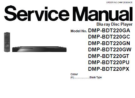
Panasonic DMP-BDT220GA/DMP-BDT220GC/DMP-BDT220GN/DMP-BDT220GW/DMP-BDT220GT/DMP-BDT220PU/DMP-BDT220PX/DMP-BDT220P/DMP-BDT220PC Service Manual
Contents:
1 Safety Precautions
1.1. General guidelines
1.2. Caution for fuse replacement
2 Warning
2.1. Prevention of Electrostatic Discharge (ESD) to Electrostatic Sensitive (ES) Devices
2.2. Precaution of Laser Diode
2.3. Service caution based on legal restrictions
3 Service Navigation
3.1. Combination of Multiple Pressing on the Remote Control
3.2. Entering Special Modes with Combination of Multiple Pressing on the Remote Control
4 Specifications
5 Location of Controls and Components
6 Operating Instructions
6.1. Taking out the Disc from BD-Drive Unit when the Disc cannot be ejected by OPEN/CLOSE button
7 Service Mode
7.1. Self-Diagnosis and Special Mode Setting
8 Service Fixture & Tools
9 Disassembly and Assembly Instructions
9.1. Unit
9.2. BD Drive
9.3. Disassembly from the traverse unit, assembly of the optical pick-up unit, and precautions on
ESD-preventive
9.4. Adjustment of BD Drive
10 Measurements and Adjustments
10.1. Service Positions
10.2. Caution for Replacing Parts
11 Block Diagram
11.1. Overall Block Diagram
11.2. Power Supply Block Diagram
11.3. Digital P.C.B. Regulator Block Diagram
11.4. Digital (Back End Section) Block Diagram
11.5. IC Pin Terminal Chart
11.6. Digital (Front End Section) Block Diagram
11.7. Analog Audio/Video Block Diagram
12 Schematic Diagram
12.1. Interconnection Schematic Diagram
12.2. Power Supply Section Schematic Diagram
12.3. FL Section Schematic Diagram
12.4. SD.USB Section Schematic Diagram
12.5. POWER SW and LED Section Schematic Diagram
12.6. AUDIO Schematic Diagram
12.7. VIDEO Schematic Diagram
12.8. ETHER.USB Section Schematic Diagram(l/2)
12.9. ETHER.USB Section Schematic Diagram(2/2)
12.10. DIGfTAL.NET Section Schematic Diagram
12.11. DDR3 Section Schematic Diagram
12.12. BP4 Section Schematic Diagram(l/2)
12.13. BP4 Section Schematic Diagram(2/2)
12.14. FE Section Schematic Diagram(l/2)
12.15. FE Section Schematic Diagram(2/2)
13 Printed Circuit Board
13.1. Power P.C.B.
13.2. Power SW P.C.B., LED P.C.B.and SDJJSB P.C.B.
13.3. Digital P.C.B.
14 Appendix for Schematic Diagram
14.1. Waveform Chart
15 Exploded View and Replacement Parts List
15.1. Exploded Views and Mechanical Replacement Parts List
15.2. Electrical Replacement Parts List |


